Building and Viewing SIP Entities in Topology View
The Topology view lets you easily build and view your main SIP entities, including IP Groups, SIP Interfaces, and Media Realms. The Topology view graphically displays these entities and the associations between them, giving you a better understanding of your SIP topology and configuration. The Topology view also lets you configure additional SIP settings that are important to your deployment such as routing and manipulation. You can use the Topology view as an alternative to configuring the entities in their respective Web pages or you can use it in combination.
To access the Topology view, do one of the following:
| ■ | Click the Topology View home |
| ■ | Click the logo, which is located in the top-left corner of the Web interface. |
The main areas of the Topology view is shown below and described in the subsequent table.
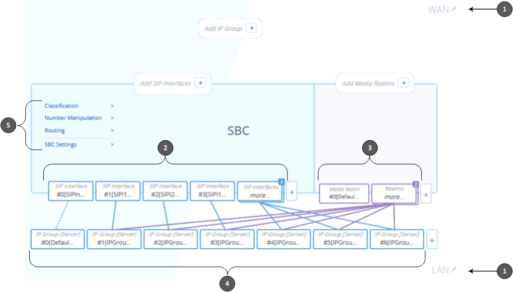
Description of Topology View
|
Item # |
Description |
||||||||||||||||||||||||||||||
|---|---|---|---|---|---|---|---|---|---|---|---|---|---|---|---|---|---|---|---|---|---|---|---|---|---|---|---|---|---|---|---|
|
1 |
Demarcation area of the topology. By default, the Topology view displays the following names to represent the different demarcations of your voice configuration:
To modify a demarcation name, do the following:
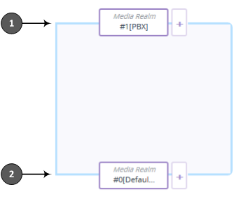
You can use demarcation to visually separate your voice network to provide a clearer understanding of your topology. This is especially useful for IP Groups, SIP Interfaces, and Media Realms, where you can display them on the top or bottom border of the Topology view (as shown in the figure below for callouts #1 and #2, respectively). For example, on the top border you can position all entities relating to WAN, and on the bottom border all entities relating to LAN.
By default, configuration entities are displayed on the bottom border. To define the position, use the 'Topology Location' parameter when configuring the entity, where Down is the bottom border and Up the top border:
|
||||||||||||||||||||||||||||||
|
2 |
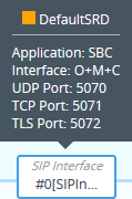
Configured SIP Interfaces. Each SIP Interface is displayed using the following "SIP Interface"-titled icon, which includes the name and row index number:
If you hover your mouse over the icon, a pop-up appears displaying the following basic information (example):
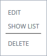
If you click the icon, a drop-down menu appears listing the following commands:
To add a SIP Interface, do the following:
The SIP Interfaces table opens with a new dialog box for adding a SIP Interface to the next available index row.
For more information on configuring SIP Interfaces, see Configuring SIP Interfaces. |
||||||||||||||||||||||||||||||
|
3 |
Configured Media Realms. Each Media Realm is displayed using the following "Media Realm"-titled icon, which includes the name and row index number:
If you hover your mouse over the icon, a pop-up appears displaying the following basic information (example):
If you click the icon, a drop-down menu appears listing the following commands:
To add a Media Realm, do the following:
The Media Realms table opens with a new dialog box for adding a Media Realm to the next available index row.
For more information on configuring Media Realms, see Configuring Media Realms. |
||||||||||||||||||||||||||||||
|
4 |
Configured IP Groups. Each IP Group is displayed using the following "IP Group [Server]" or "IP Group [User]" titled icon (depending on whether it's a Server- or User-type IP Group respectively), which includes the name and row index number (example of a Server-type):
If you hover your mouse over the icon, a pop-up appears displaying the following basic information (example):
If you click the icon, a drop-down menu appears listing the following commands:
To add an IP Group, do the following:
The IP Groups table opens with a new dialog box for adding a IP Group to the next available index row.
For more information on configuring IP Groups, see Configuring IP Groups. IP Group icons also display connectivity status with Server-type IP Groups:
The line type connecting between an IP Group and a SIP Interface indicates whether a routing rule has been configured for the IP Group. A solid line indicates that you have configured a routing rule for the IP Group; a dashed line indicates that you have yet to configure a routing rule. Note:
|
||||||||||||||||||||||||||||||
|
5 |
Links to Web pages relating to commonly required SBC configuration:
|


 when no SIP Interfaces exist on a topology border, or as
  when there are no SIP Interfaces at all.
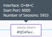
 when no Media Realms exist on a topology border, or as
  when there are no Media Realms at all.
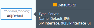
 when no IP Groups exist on a topology border, or as
 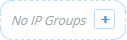 when there are no IP Groups at all.
 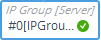 (Green with check mark): Keep-alive is successful and connectivity exists with IP Group.
 (Red with "x"): Keep-alive has failed and there is a loss of connectivity with the IP Group.